

The calculation methods implemented in nPro for pipe sizing and for determining pressure and heat losses were compared with the planning software isoConnect developed by the pipe manufacturer isoplus. This page presents the results for three comparison cases (single pipe and twin pipe, different network temperatures).
Objective and Approach
Two calculation variables are of central importance for the design of district heating networks: the pressure loss (which governs both the pipe sizing, i.e. the choice of nominal diameter, and the design of the network pumps) and the heat loss (which governs the efficiency of the network). To verify the methods implemented in nPro, the results were compared with the isoConnect software from the pipe manufacturer isoplus.
To ensure that only methodological differences become visible, identical pipe types and identical boundary conditions were used in both programs. This means in particular the same ambient and ground temperatures, the same thermal conductivity of the insulation, the same pipe roughness, the same pipe spacing and the same burial depth or cover.
All percentage deviations given below refer to the isoConnect results as the reference value.
Boundary Conditions
General Boundary Conditions
The following boundary conditions apply to all comparison calculations and were set identically in nPro and isoConnect. Radiation effects were not considered in either tool.
| Parameter | Value |
|---|---|
| Supply/return temperature | 80/40 °C (cases 1 and 2) and 110/70 °C (case 3) |
| Ambient air temperature | 8 °C |
| Ground temperature | 8 °C |
| Radiation considered | no |
| Thermal conductivity of the ground | 1.5 W/(m K) |
| Wind speed (above-ground pipes) | 3 m/s |
| Cover (for buried pipes) | 1.0 m |
| Heat transfer medium | water |
| Length of each pipe | 100 m |
| Maximum pressure gradient (sizing) | 300 Pa/m |
Cases Investigated
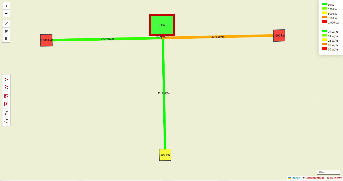
Three cases are compared, differing in pipe type and network temperature. Within each case, three pipes with a length of 100 m each are considered, differing in transported capacity and installation type.
| Case | Pipe type | Supply/return temperature | Pipe 1 | Pipe 2 | Pipe 3 |
|---|---|---|---|---|---|
| 1 | Single pipe | 80/40 °C | buried, 1000 kW | buried, 500 kW | above ground, 1000 kW |
| 2 | Twin pipe | 80/40 °C | buried, 1000 kW | buried, 500 kW | buried, 750 kW |
| 3 | Single pipe | 110/70 °C | buried, 1000 kW | buried, 500 kW | above ground, 1000 kW |
Pipe-Specific Parameters
The properties of the pipes differ depending on the pipe type. The same values were used in both programs.
| Parameter | Single pipe (cases 1 and 3) | Twin pipe (case 2) |
|---|---|---|
| Product designation / pipe type | isoplus Konti (normal), steel | isoplus Konti (single reinforced), steel |
| Insulation series | Standard | 1x reinforced |
| Thermal conductivity of insulation (λ50) | 0.024 W/(m K) | 0.024 W/(m K) |
| Pipe roughness | 0.1 mm | 0.1 mm |
| Spacing between service pipes | 150 mm | 25 mm (DN 80) and 20 mm (DN 65) |
Case 1: Single Pipe at 80 °C Supply Temperature
The first case represents a district heating network with separately buried supply and return pipes. The comparison covers the selected nominal diameter, the specific pressure loss and the specific heat loss. Since nPro reports a single pressure loss value per trench while isoConnect reports separate values for supply and return, the mean of both pipes is used for isoConnect.
| Pipe | nPro | isoConnect | Deviation |
|---|---|---|---|
| Buried, 1000 kW | DN 80 | DN 80 | 0 % |
| Buried, 500 kW | DN 65 | DN 65 | 0 % |
| Above ground, 1000 kW | DN 80 | DN 80 | 0 % |
| Pipe | nPro | isoConnect | Deviation |
|---|---|---|---|
| Buried, 1000 kW | 168 Pa/m | 167.9 Pa/m | 0.1 % |
| Buried, 500 kW | 104 Pa/m | 104.2 Pa/m | -0.2 % |
| Above ground, 1000 kW | 168 Pa/m | 167.9 Pa/m | 0.1 % |
| Pipe | nPro | isoConnect | Deviation |
|---|---|---|---|
| Buried, 1000 kW | 22.9 W/m | 23.6 W/m | -3.2 % |
| Buried, 500 kW | 22.1 W/m | 23.0 W/m | -3.7 % |
| Above ground, 1000 kW | 27.6 W/m | 26.7 W/m | 3.6 % |
Both programs select the same nominal diameter for all three pipes. The deviation in specific pressure loss is around 0.2 %. The heat losses also agree well, with deviations below 4 %. For the buried pipes nPro calculates slightly lower losses, for the above-ground pipe slightly higher losses than isoConnect.
Case 2: Twin Pipe at 80 °C Supply Temperature
In twin pipe systems, supply and return are embedded in a common casing pipe. This results in considerably lower heat losses than for single pipes, while the heat transfer between the two service pipes must be accounted for in the calculation.
| Pipe | nPro | isoConnect | Deviation |
|---|---|---|---|
| Buried, 1000 kW | DN 80 | DN 80 | 0 % |
| Buried, 500 kW | DN 65 | DN 65 | 0 % |
| Buried, 750 kW | DN 80 | DN 80 | 0 % |
| Pipe | nPro | isoConnect | Deviation |
|---|---|---|---|
| Buried, 1000 kW | 168 Pa/m | 167.9 Pa/m | 0.1 % |
| Buried, 500 kW | 104 Pa/m | 104.2 Pa/m | -0.2 % |
| Buried, 750 kW | 96 Pa/m | 96.2 Pa/m | -0.2 % |
| Pipe | nPro | isoConnect | Deviation |
|---|---|---|---|
| Buried, 1000 kW | 13.3 W/m | 12.9 W/m | 2.9 % |
| Buried, 500 kW | 12.1 W/m | 11.8 W/m | 2.6 % |
| Buried, 750 kW | 13.3 W/m | 12.9 W/m | 2.9 % |
For the twin pipe system as well, both programs select the same nominal diameter, and the pressure losses deviate by less than 0.2 %. The heat losses calculated in nPro are about 3 % higher than those from isoConnect.
Case 3: Single Pipe at 110 °C Supply Temperature
The third case examines whether the agreement is maintained at higher network temperatures and thus larger temperature differences to the ground. Pipe type and installation correspond to case 1, while the network temperatures were raised to 110/70 °C.
| Pipe | nPro | isoConnect | Deviation |
|---|---|---|---|
| Buried, 1000 kW | DN 80 | DN 80 | 0 % |
| Buried, 500 kW | DN 65 | DN 65 | 0 % |
| Above ground, 1000 kW | DN 80 | DN 80 | 0 % |
| Pipe | nPro | isoConnect | Deviation |
|---|---|---|---|
| Buried, 1000 kW | 167 Pa/m | 161.8 Pa/m | 3.2 % |
| Buried, 500 kW | 103 Pa/m | 99.9 Pa/m | 3.2 % |
| Above ground, 1000 kW | 167 Pa/m | 161.8 Pa/m | 3.2 % |
| Pipe | nPro | isoConnect | Deviation |
|---|---|---|---|
| Buried, 1000 kW | 36.1 W/m | 37.3 W/m | -3.3 % |
| Buried, 500 kW | 34.8 W/m | 36.2 W/m | -3.7 % |
| Above ground, 1000 kW | 43.6 W/m | 42.1 W/m | 3.5 % |
The nominal diameters again agree for all three pipes. For the heat losses, the deviation remains at around 3 to 4 %, the same level as at 80 °C supply temperature, and the same pattern emerges: nPro calculates slightly lower losses for buried pipes and slightly higher losses for above-ground pipes. For the pressure loss, the deviation increases from about 0.2 % in case 1 to just over 3 %. This is caused by the properties of water, which differ more strongly between the programs at high temperatures and enter the calculation of mass flow and pipe friction via density and viscosity.
Discussion of the Deviations
In all three comparison cases, nPro and isoConnect select the same nominal diameters. The specific pressure losses deviate by no more than 0.2 % at 80/40 °C and by just over 3 % at 110/70 °C. The decisive factors here are the temperature-dependent properties of water and the determination of the friction factor, whose influence increases with rising network temperature. The specific heat losses also agree well, with deviations of around 3 to 4 %, whereby nPro calculates slightly lower values for buried single pipes and slightly higher values for above-ground pipes. This reflects different approaches to the external heat transfer as well as to the ground thermal resistance and the mutual thermal influence between supply and return. For planning practice, these differences are well within the uncertainty that already results from the assumptions about ground properties, burial depth and operating temperatures.