

The pressure calculation forms the basis of network design in nPro. Since it is based on a system of node and loop equations, meshed networks can be designed and simulated just like branched networks. Loops are detected and dimensioned automatically.
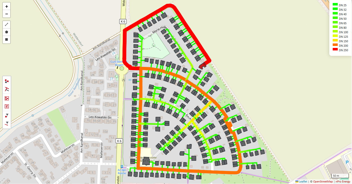
What distinguishes meshed from branched networks?
In a branched network, there is exactly one flow path between the energy centre and each consumer. The volume flow in each pipe section therefore follows directly from the sum of the downstream demands.
In a meshed network, by contrast, the pipes form closed loops, so a consumer can be supplied via several flow paths. How the volume flow is distributed between the individual branches of a loop no longer follows from the network topology alone, but from the hydraulic equilibrium: the pressure losses around each loop must sum to zero. Since the pressure loss in a pipe depends non-linearly on the volume flow, this results in a non-linear system of equations that is solved iteratively.
Pressure calculation as the basis of network design
The pressure calculation forms the basis for designing the heating network: the required nominal pipe diameters and the sizing of the circulation pump follow from the volume flows and pressure losses. Because nPro determines the pressures using a system of equations for the entire network, rather than by summing up step by step along a single branch, this approach works for meshed networks just as it does for branched ones.
Setting up the system of equations
The system of equations consists of two types of equation:
- Node equations (mass conservation): at each node, the sum of the incoming mass flows equals the sum of the outgoing mass flows.
- Loop equations (pressure losses): around each closed loop, the pressure losses sum to zero, taking the flow direction into account.
The hydraulic specifications of the network enter the system of equations as boundary conditions:
- the pressure at the energy centre, defined by the set point of the pressure maintenance in the return line
- the pressure loss of the energy centre, which determines the supply pressure at the feed-in point
- the pressure losses of the heat transfer stations, which couple the supply and return lines at each building
- the pressure losses of pipe fittings as well as the geodetic elevations of the network nodes
- the minimum pressure that must be maintained at the critical point of the network
The resulting system of equations is solved using the Newton-Raphson method. The supply and return lines are treated as separate networks and coupled via the heat transfer stations and the energy centre.
How the minimum pressure is derived from the vapour pressure of the heat transfer medium and the safety margins, and how the pressure curves towards the critical point are visualised, is described in the article on the pressure calculation in heating networks.
Detection and dimensioning of loops
nPro detects loops automatically from the network geometry you have drawn. There is no need to mark rings manually.
During dimensioning, all pipe sections within a loop are assigned the same nominal diameter, namely the largest diameter required anywhere in that loop. Since the flow direction within a loop can reverse depending on the load case, every section must be dimensioned for the most unfavourable load that occurs.
Results
The same result variables are available for meshed networks as for branched networks:
- Volume flows and flow directions in all pipe sections and loops
- Temperature profiles in the supply and return lines
- Pressure curves and absolute pressures throughout the network
- Nominal diameters, utilisation and spare capacity for each pipe section
The results can be visualised on the map and exported as an Excel file or GIS and CAD file.