

5GDHC networks can be operated passively, i.e. without a central network pump, or actively with a central pump in the energy hub. nPro can calculate both variants. In both cases, the pipes are sized like in conventional district heating networks based on the pressure gradient and the flow velocity. nPro then sizes the central pump or the decentralized pumps at the buildings and indicates when a building pump exceeds the pump head of the intended heat pumps.
Passive and active 5GDHC networks
In a passive network, there is no network pump. The circulation pumps of the decentralized heat pumps move the water through the network and the source themselves, e.g. a borehole heat exchanger field. The energy hub is hydraulically passive. Each building pump has to overcome the pressure loss along its path through the network and the energy hub.
In an active network, a central pump in the energy hub circulates the water, as in a conventional district heating network. A differential pressure is then available at each building, and the heat pumps draw the water via their substation. The pump head of the central pump results from the pressure loss up to the critical point, the pressure loss of the substation and the pressure loss of the energy hub. How nPro sizes the central pump is described in the article on meshed district heating networks; the approach applies to tree-shaped networks in the same way.
In nPro, the concept is selected via the circulation pump setting: central pump for active networks, decentralized pumps for passive networks. Which concept is more favorable depends on the network. Decentralized pumps mainly save pumping electricity when the buildings are at very different distances from the source, because each pump is only sized as large as its location requires. In compact networks, the lower efficiency of many small pumps can offset this advantage. Both variants can be compared directly in nPro.
How are the pipes sized?
Pipe sizing is determined by the design criteria in the heating network settings: the maximum pressure gradient (Pa/m) and the maximum flow velocity. For each pipe, the flow rate is determined from the design load, and the smallest nominal diameter that meets both criteria is selected. The method is therefore the same as for conventional district heating networks and applies equally to passive and active networks. In meshed networks, the flow distribution in the ring is first determined cost-optimally.
The pipe selection can be influenced via the pipe parameter table or by uploading your own pipe data. By adding or deleting nominal diameters, certain pipes can be prioritized or excluded. In addition, individual pipes can be assigned a fixed nominal diameter on the map.
How is the pump head of the decentralized pumps calculated?
In a passive network, each building station pumps in its flow direction against the differential pressure at its node. The pump head of a building pump consists of:
- the pressure loss of the energy hub, calculated from the borehole parameters for borehole heat exchangers, otherwise as a lump-sum value,
- the pressure losses in supply and return along the path between the energy hub and the building,
- the surcharge for pipe installations on the pipe pressure losses.
The pressure loss of the heat pump itself (evaporator or heat exchanger) belongs to the building installation and is not included in the stated pump head. If the available differential pressure at a building exceeds the requirement, e.g. near a feed-in station, the station throttles and the pump head is zero.
The pump heads are determined from the hydraulic network calculation. How nPro chooses between design and simulation, especially in meshed networks, is described in the article on meshed district heating networks. For buildings that are cooled in summer and thereby release heat into the network, a summer point in time is additionally considered, since the flow directions can then reverse.
Which settings are required?
The hydraulic settings are made in the Hydraulics and pressure losses dialog.
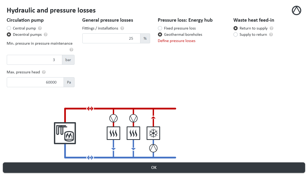
- Circulation pump: central pump for active networks, decentralized pumps for passive networks.
- Max. pump head (only with decentralized pumps): the pump head that the intended heat pumps can provide. It is used to check the results.
- Pipe installations: percentage surcharge on the pipe pressure losses for fittings and valves.
- Pressure losses: energy hub: either a lump-sum pressure loss or calculated from the parameters of the geothermal probes. For borehole heat exchangers, either a specific heat extraction rate can be specified (the number of boreholes is then calculated automatically) or the number of boreholes directly.
- Waste heat feed-in: defines how buildings that release heat into the network (e.g. when cooling) are hydraulically connected: from return to supply (with their own feed-in pump) or from supply to return (hydraulically like a consumer).
Since the pressure loss of the energy hub is part of the pump head of every building in a passive network, it should be well below the maximum pump head of the building pumps. The design criteria for pipe sizing (pressure gradient and flow velocity) are defined in the heating network settings.
Example: Borehole field with decentralized pumps
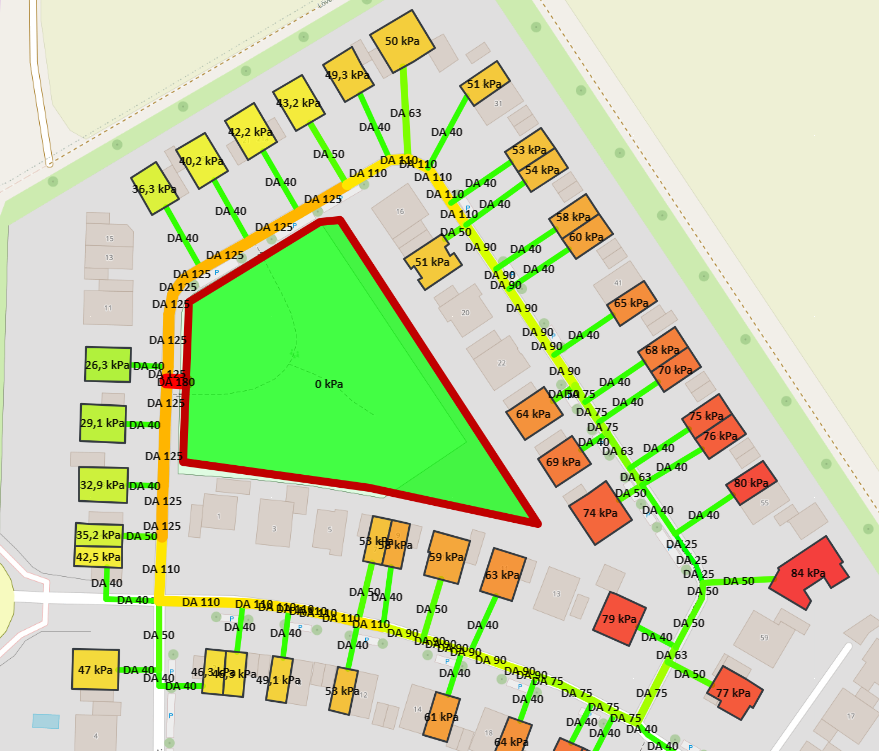
The figure shows a passive 5GDHC network whose source is a borehole heat exchanger field in the center of the district. nPro shows the required pump head of the decentralized pump at each building.
The pump head increases with the distance from the borehole field: the buildings directly west of the field need around 26 kPa, while the buildings at the eastern end of the network require up to 84 kPa. The pipe diameters decrease from the borehole field outwards, from DA 180 at the connection of the field to DA 40 at the house connections.
Two things can be read from this for the design: first, the map directly shows which buildings form the critical paths. If the pump head there exceeds the maximum pump head of the intended heat pumps, larger nominal diameters along the path or a different location of the source will help. Second, the example shows why decentralized pumps are a good fit here: the buildings are at very different distances from the borehole field, and each pump only has to provide the pump head required at its own location.
Video tutorial on 5GDHC networks
A detailed video tutorial on calculating 5GDHC networks can be found here:
