
nPro covers the full design process for heating networks, from the energy demands of individual buildings through automatic pipe dimensioning to hydraulic and thermal simulation over the year.
Overview
| Area | Features |
|---|---|
| Buildings | Enter building data manually or via GIS import, define building types and retrofit states |
| Energy demands | Hourly profiles for space heating, domestic hot water, cooling, user electricity and electric mobility |
| Network design | Network temperatures, simultaneity, heat transfer fluid, ground parameters, automatic pipe dimensioning |
| Hydraulics | Circulation pumps, pressure losses, topography, waste heat feed-in, meshed networks |
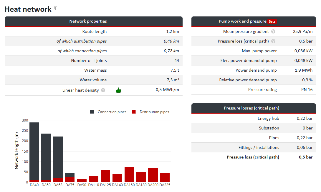
| Results | Pipe lengths, nominal diameters, volume flows, heat losses, linear heat density, pumping energy |
Building energy demands
- Several calculation methods: annual demand, heat load or a combination of both; for existing buildings also based on the fuel consumed (heating oil, natural gas, pellets, wood chips and others)
- All demand types: space heating, domestic hot water, space cooling, process cooling, user electricity and electric mobility
- Extensive profile database: consistent demand profiles in hourly resolution, generated in just a few clicks
- Your own profiles: time series and daily profiles can be imported, adjusted and exported
- Retrofit scenarios: insulation measures and heating system replacements can be modelled for each building
Network design
- Network temperatures: constant, variable or based on an imported profile
- Simultaneity factor: Winter et al., ISSO 7 (residential and commercial buildings), your own profile, or no simultaneity; for mixed districts, residential buildings can be considered separately
- Heat transfer fluid: water or brine with an adjustable glycol content
- Heat losses taking installation depth, pipe spacing and the thermal conductivity of the ground into account
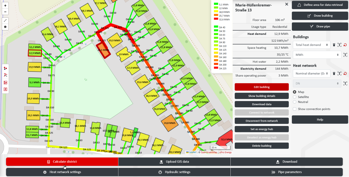
- Automatic pipe dimensioning for the network you have drawn, with individual sections remaining adjustable by hand
Hydraulics and pipe data
- Network topology: in addition to branched and tree-shaped networks, meshed networks with ring mains can also be calculated
- Circulation pumps: central or decentralised, with a maximum pump head
- Pressure losses from pipe fittings, the energy centre, geothermal probes and elevation differences
- Waste heat feed-in into the supply or return line
- Pipe library with steel and plastic pipes from LOGSTOR, ISOPLUS and BRUGG Pipes; your own pipe data can be imported
Analysing results
- Key figures for each pipe section: nominal diameter, length, pressure loss, volume flow, flow velocity, utilisation and spare capacity for connecting further buildings
- Network key figures: total pipe length, linear heat density, heat losses, pumping energy, distribution of pipe diameters
- Visualisation on the map: freely selectable building and network parameters directly in the network layout
- Profile views: annual profile, monthly values, load duration curve and heat map
- Export of all results as an Excel file, GIS and CAD file or report