Energy flows in 5th generation district heating and cooling networks
Note: Not all parts of the calculation logic shown correspond to the latest software version. However, most of the technical description is still applicable.
Calculation approach
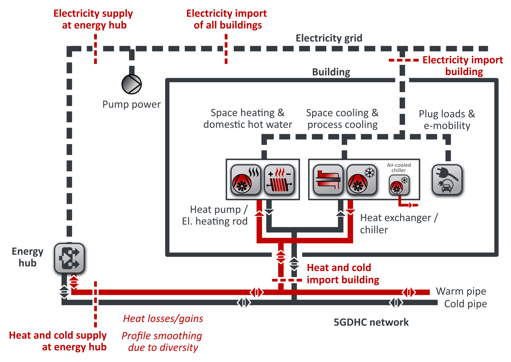
The calculation of 5GDHC networks in nPro is illustrated in Figure 1: The heat demand for space heating and domestic hot water is covered in each building with a heat pump. The evaporator of the heat pump is connected to the 5GDHC network. In addition to the heat pump, an electric heating rod can be installed. The heating rod covers peak loads of the space heating demand and makes it possible to size the capacity of the heat pump smaller.
The cooling demands for space cooling and process cooling are covered either by a chiller or a heat exchanger (passive cooling). The chiller is connected to the 5GDHC network at the condenser side and the waste heat is completely fed into the 5GDHC network. If a heat exchanger is installed (passive cooling), it is also thermally connected to the 5GDHC network and feeds all waste heat into the heat network as well. In addition, an air-cooled chiller can be installed. The air-cooled chiller covers peak loads and its waste heat is dissipated to the environment and not fed into the 5GDHC network. The total electricity demand of a building consists of:
- Electricity demands for the heat pump and the electric heating rod (if available),
- electricity demands for the chiller that is connected to the 5GDHC network (if available),
- electricity demands for the air-cooled chiller (if available), and
- the sum of the plug loads and e-mobility demands.
Within the building, waste heat from the cooling system (chiller/heat exchanger) can be used directly at the evaporator of the heat pump. In this way, if there is a simultaneous demand for heating and cooling, part of the demands can be balanced in the building. Only the remaining, unbalanced demand must be imported from the 5GDHC network. These remaining heating and cooling demands describe the heat and cold imports of the building (net demands). As long as at least one building has a net heat demand and at least one other building has a net cooling demand at any given time, some demands can be balanced in the 5GDHC network. This means that waste heat from one building (with net cooling demands) is used by another building to meet its net heat demands. This reduces the heat or cold generated at the energy hub. To calculate the heat and cold feed-in profile at the energy hub, the simultaneity factor is taken into account, which leads to a profile smoothing. Heat losses are neglected for the 5GDHC network. For network temperatures close to the ground temperature, this assumption is justified. For very high (e.g., 40 °C) or low network temperatures (e.g., below 0 °C), this assumption may no longer be justified, especially if uninsulated pipes are used. For the electricity grid, all electricity imports of the buildings are added up, which then represent the total electricity import of all buildings. No losses are considered for the power grid. The pumping power of the hydraulic pumps is added up to determine the electric power demand covered by the energy hub.
 English
 Deutsch


