Sizing of heat transfer stations in district heating networks
The dimensioning of heat transfer stations in district heating networks largely depends on the type of domestic hot water preparation, the use of buffer storage tanks, and the prioritization between space heating and hot water preparation. Depending on the selected concept, different requirements arise for the maximum heat capacity supplied by the district heating network as well as for the dimensioning of the transfer station.
Fundamentals
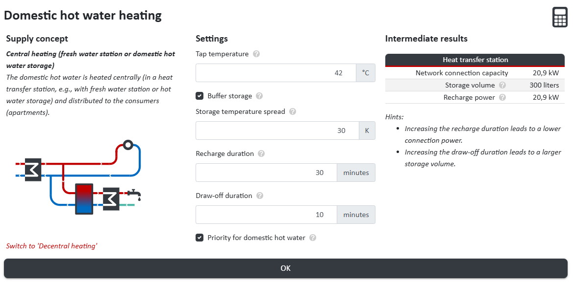
For the design of heat transfer stations, both the heating capacity for space heating and the capacity required for domestic hot water preparation must be considered and evaluated separately. Depending on whether hot water preparation is centralized or decentralized, whether a buffer storage tank is used, and whether a priority control for domestic hot water preparation is implemented, different design cases arise. In the following, six typical variants of domestic hot water preparation in district heating networks are distinguished, which can be selected in the nPro tool.
| Concept | Buffer storage | Priority control |
|---|---|---|
| Central DHW preparation using fresh water stations | yes | yes |
| yes | no | |
| no | yes | |
| no | no | |
| DHW preparation using apartment stations | yes | yes |
| no | yes |
Calculation of Domestic Hot Water Capacity
A key step in the design calculation is the determination of the domestic hot water capacity of a building. Simultaneity effects, centralized and decentralized hot water preparation, and the maximum hot water demand are taken into account. First, the simultaneity factor of domestic hot water draw-offs \(f_{GLZ}(housing units)\) is determined depending on the number of housing units \(N_{WE}\). This factor describes how many tapping events occur simultaneously across several apartments. If hot water preparation is centralized or partly centralized, the number of simultaneous tapping events is calculated as follows:
$$n_{draw-offs} = N_{WE} \cdot f_{GLZ}$$
Next, the share of the domestic hot water capacity that is provided decentrally \(A_{decentral}\) is determined. This value ranges between 0 and 1. The capacity of a single tapping event (with full temperature lift) is calculated as follows:
$$\dot{Q}_{single,tap,full} = c_p \cdot \rho \cdot \dot{V}_{DHW} \cdot (T_{tap} - T_{cold})$$
The centrally supplied share of the capacity per tapping event is calculated as:
$$\dot{Q}_{single,tap,full,central} = \dot{Q}_{single,tap,full} \cdot (1 - A_{decentral})$$
The total centrally supplied domestic hot water capacity results from:
$$\dot{Q}_{central,total} = \dot{Q}_{single,tap,full,central} \cdot n_{draw-offs}$$
If decentralized instantaneous water heaters / under-sink units are installed, the total installed electrical capacity of these devices is given by:
$$\dot{Q}_{el,decentral,total} = \dot{Q}_{single,tap,decentral} \cdot N_{WE}$$
For result presentation, the maximum domestic hot water demand is additionally calculated:
$$\dot{Q}_{dhw,max} = \dot{Q}_{single,tap,full} \cdot N_{WE} \cdot f_{GLZ}$$
Calculation of the Domestic Hot Water Buffer Storage
If no storage tank is provided for domestic hot water preparation, the required capacity of the central hot water system corresponds to the maximum hot water demand. If a buffer storage tank is installed, the required capacity of the central hot water system is determined based on the charging capacity of the buffer storage. The charging capacity depends on the draw-off capacity, the draw-off duration, and the charging time of the storage tank. First, the draw-off volume flow is calculated:
$$\dot{V}_{draw-off} = \frac{\dot{Q}_{DHW,central,total}}{c_p \cdot \rho \cdot \Delta T_{spread}}$$
Next, the draw-off volume is calculated:
$$V_{draw-off} = \dot{V}_{draw-off} \cdot t_{draw-off}$$
The required storage volume results from:
$$V_{storage} = \frac{V_{draw-off}}{\eta_{storage}}$$
A storage efficiency of 85 % is assumed, meaning that the usable volume corresponds to 85 % of the actual storage volume. The real storage volume \(V_{storage,real}\) is then adjusted to discrete storage sizes. The smallest available volume is 200 liters. Volumes up to 1000 liters are adjusted in steps of 100 liters; up to 2000 liters in steps of 200 liters; up to 5000 liters in steps of 500 liters; and above that in steps of 1000 liters. The charging volume flow is therefore:
$$\dot{V}_{charging} = \frac{V_{storage,real}}{t_{charging}}$$
The charging capacity of the storage tank then follows:
$$\dot{Q}_{charging} = c_p \cdot \rho \cdot \dot{V}_{charging} \cdot \Delta T_{spread}$$
Calculation of Heating Capacity (Space Heating)
To calculate the heating capacity (space heating), the maximum peak load of the space heating demand is first determined. The space heating demand profile may be divided into base load and peak load (if a peak-load generator is activated). Subsequently, the simultaneity factor for space heating is determined. Buildings with the building type "residential" or "mixed-use" are included based on the number of housing units. All other buildings are included in the calculation with either the value 1 or 0 depending on the selected setting. This means that non-residential buildings are included with 1 or 0 regardless of the number of configured usage units. From the sum, the simultaneity factor for space heating is determined according to the selected method. The maximum peak load is then multiplied by the simultaneity factor to obtain the effective heating capacity. If decentralized domestic hot water preparation using apartment stations is implemented, a priority control of hot water preparation over space heating is additionally considered. This means that the effective heating capacity may be further reduced depending on the number of simultaneous tapping events and the number of housing units.
Determination of the Capacity of the Heat Transfer Station
For the design of the heat transfer station, the maximum capacities drawn from the district heating network for space heating and domestic hot water must first be determined. In a first step, it is determined which share of the capacity can be covered directly by the district heating network compared with the share that must be provided by booster heat pumps or booster instantaneous heaters. This share results from the network temperature, the COP profiles of the heat pumps, and the demand profiles. If assumptions must be made regarding the timing of the domestic hot water peak load, the estimation is performed conservatively to ensure that the heat pump is not undersized even in unfavorable conditions. In the case of centralized hot water preparation using fresh water stations with priority control, only the higher value of the two loads (space heating or hot water) is used for the dimensioning of the heat transfer station.
For the final design of the heat transfer station, the maximum of a) the sum of the maximum loads for space heating and domestic hot water and b) the maximum of the cumulative load profile (space heating, domestic hot water and possibly cooling) is used. This means that both the static peak load and the maximum peak load from the load profiles are considered. In most cases, the static peak load is relevant for the dimensioning of the heat transfer station. However, in cases of balancing effects between heating and cooling demands or large cooling demands, the maximum peak load from the load profiles may become relevant.
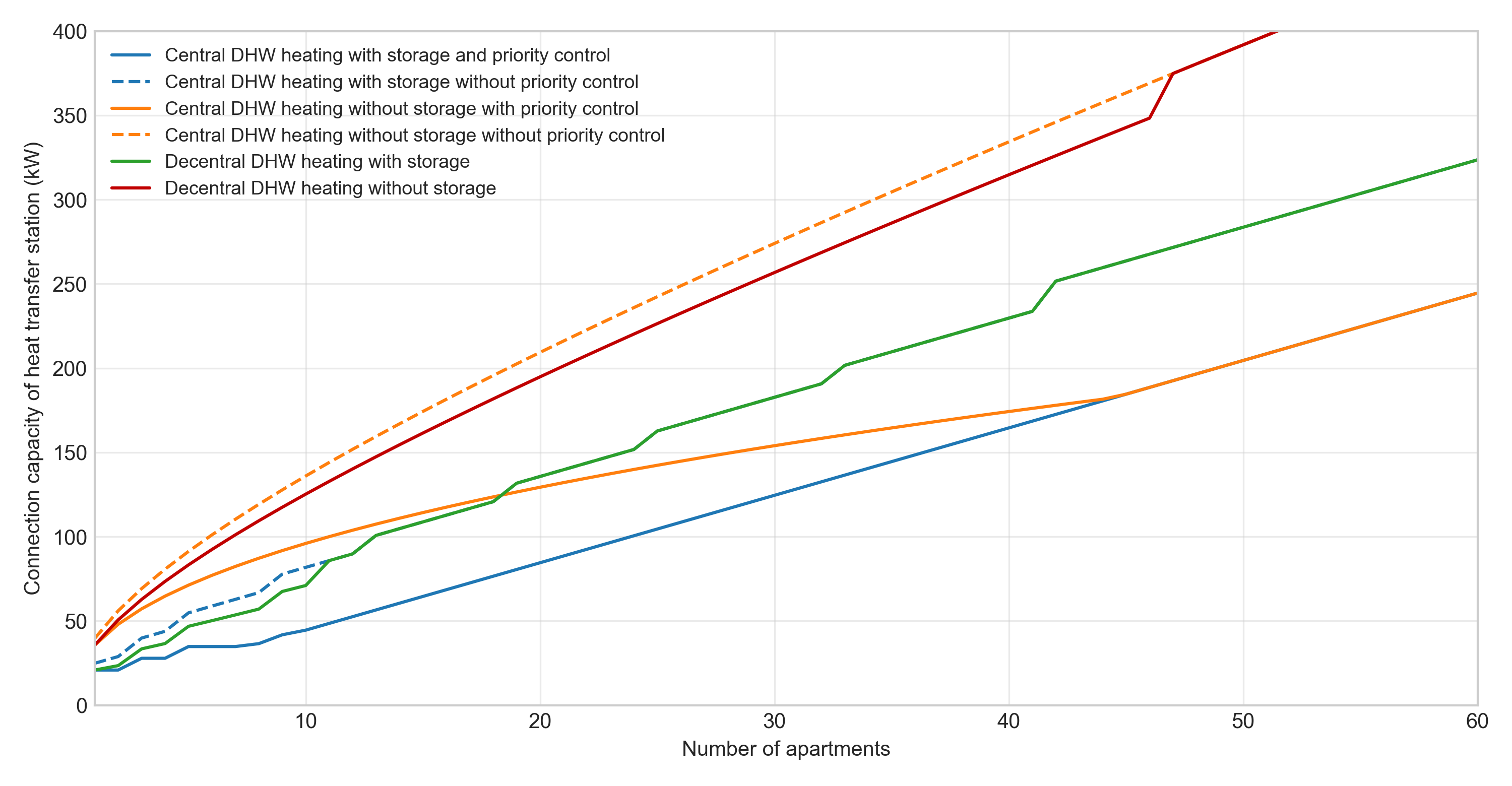
Heat Transfer Station Capacity Depending on the Number of Housing Units
Figure 2 shows the capacity of the heat transfer station depending on the number of housing units in a district heating network. The figure is based on several assumptions: for example, the heating load per housing unit is assumed to be 4 kW. It can be seen that the required capacity increases with the number of housing units, but not linearly, instead with decreasing slope. This occurs because the simultaneity factor for domestic hot water decreases as the number of housing units increases, resulting in a lower additional capacity requirement per additional housing unit.
 English
 Deutsch


