Pipe dimensioning for heat networks in nPro
On this page you will learn how to dimension pipe diameters of heating networks, cooling networks and 5th generation district heating and cooling (5GDHC) networks using the nPro tool.
Pipe sizing and dimensioning in nPro
In the nPro tool, the pipe diameters of heating networks can be estimated and dimensioned in the early planning phase. The procedure for this is as follows: In the pipe dimensioning of nPro (in the module "Load profiles and heat network"), the network pipe, that shall be dimensioned, is selected on the left-hand side (building selection): In the nPro tool it is assumed that the heat network has a star topology (a star topology has no meshes). In the building list, all buildings are selected that are supplied via the pipe that is dimensioned. This is illustrated in Figure 1: In the depicted district, 3 groups of buildings are supplied via a heat network by an energy hub. In order to dimension pipe I of the heating network, all buildings in the district are selected, since pipe I supplies all buildings in the district. Consequently, this pipe has the largest pipe diameter in the heating network. Only building A is selected for sizing pipe II, since pipe II only supplies this single building. Accordingly, for the dimensioning of pipe III, buildings B and C would be selected.
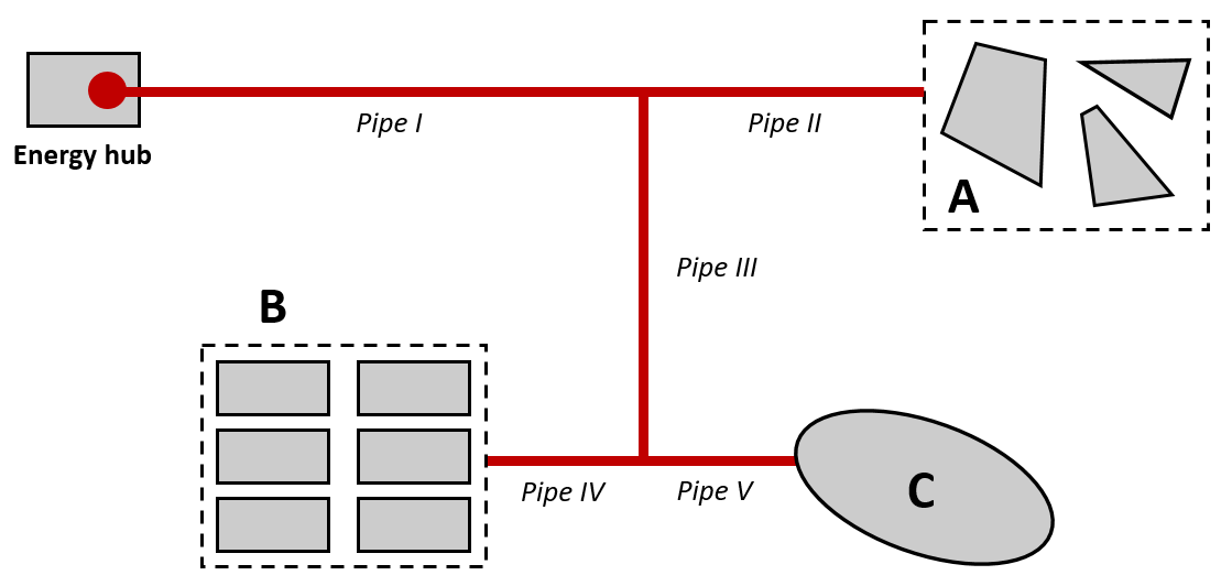
Figure 1: Exemplary district with heating network in star topology.
How is the optimum diameter calculated?
Design recommendations from pipe manufacturers are stored in the nPro tool. The manufacturer guidelines are used to determine the optimal pipe diameter for a specific mass flow. In principle, there is no clear physically justifiable design decision. The calculation approach underlying these design recommendations is generally based on cost assumptions for the installation of the heating network, the material price for the pipes and other techno-economic cost influences. nPro suggests a nominal diameter for pre-dimensioning, which is determined on the basis of the manufacturer recommendations. Nevertheless, other nominal diameters should be considered. For this purpose, a detailed analysis of several pipe diameters can be created in nPro. Here, key figures for pumping work and maximum pressure gradients are calculated and graphically displayed. For the calculation of the pressure gradient in the laminar range up to a Reynolds number of 2300, the pressure loss coefficient is determined with the formula 64/Reynolds number. For the turbulent range with a Reynolds number greater than 2300, the iterative approach of Colebrook is used. The transition range between Re=2300 and Re=5000 is deliberately not attempted to be calculated. Instead, a "jump" in the pressure loss coefficient at Re=2300 is assumed, which has the advantage of additional safety in the calculation of the pressure loss.
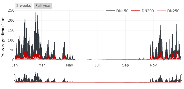
Figure 2: Analysis of pressure gradients in the district heating network pipe with nPro.
Validation of the pressure loss and diameter calculation
The calculation methods in nPro were compared and validated with different hydraulic calculation tools. As an example, Tables 1 to 3 show a quantitative comparison of the pressure loss calculation in nPro and data from the pipe manufacturer ENERPIPE. The ENERPIPE data are based on a company brochure with data for a CaldoPEX pipe at 80 °C supply temperature and 60 °C return temperature (brochure: "ENERPIPE - Nahwärmetechnik die ankommt.", 01/2021, pp. 34-35). Tables 4 to 7 present a quantitative comparison between the pressure loss calculations of nPro and the results of the online tool druckverlust.de. Tables 4 and 5 specifically validate the results for laminar flows and Tables 6 and 7 for turbulent flows.
Table 1: Comparison of pressure gradients calculated with nPro and the values given by ENERPIPE for a volume flow of 12.5 l/s (temperature difference: 20 K, thermal power: 1022.9 kW) and a surface roughness of 0.007 mm.
| Inner diameter |
nPro |
ENERPIPE |
Deviation |
| 90 mm |
300 Pa/m |
297.1 Pa/m |
1.0 % |
| 102.2 mm |
161 Pa/m |
158.8 Pa/m |
1.4 % |
| 114.6 mm |
92 Pa/m |
90.6 Pa/m |
1.5 % |
Table 2: Comparison of pressure gradients calculated with nPro and the values given by ENERPIPE for a volume flow of 20 l/s (temperature difference: 20 K, thermal power: 1636.6 kW) and a surface roughness of 0.007 mm.
| Inner diameter |
nPro |
ENERPIPE |
Deviation |
| 114.6 mm |
219 Pa/m |
217.3 Pa/m |
0.8 % |
| 130.8 mm |
115 Pa/m |
113.3 Pa/m |
1.5 % |
Table 3: Comparison of pressure gradients calculated with nPro and the values given by ENERPIPE for a volume flow of 1 l/s (temperature difference: 20 K, thermal power: 81.8 kW) and a surface roughness of 0.007 mm.
| Inner diameter |
nPro |
ENERPIPE |
Deviation |
| 32.6 mm |
411 Pa/m |
403.6 Pa/m |
1.8 % |
| 40.8 mm |
139 Pa/m |
135.1 Pa/m |
2.9 % |
| 51.4 mm |
46 Pa/m |
44.1 Pa/m |
4.3 % |
Table 4: Comparison of pressure gradients for a laminar flow calculated with nPro and the results from the tool druckverlust.de for a surface roughness of 0.15 mm (Temperature: 70°C, Temperature difference: 20 K) .
| Inner diameter |
Reynolds number |
nPro |
druckverlust.de |
Abweichung |
| 21.7 mm |
1700 |
1.18 Pa/m |
1.25 Pa/m |
5.4 % |
| 27.3 mm |
1300 |
0.452 Pa/m |
0.447 Pa/m |
1.2 % |
| 50 mm |
1300 |
0.074 Pa/m |
0.075 Pa/m |
0.9 % |
| 100 mm |
2000 |
0.014 Pa/m |
0.013 Pa/m |
5.7 % |
| 170 mm |
300 |
0.00043 Pa/m |
0.000425 Pa/m |
1.1 % |
Table 5: Comparison of pressure gradients for a laminar flow calculated with nPro and the results from the tool druckverlust.de for an inner diameter of 40 mm (Temperature: 70 °C, Temperature difference: 20 K) and a surface roughness of 0.15 mm.
| Flow velocity |
Power |
nPro |
druckverlust.de |
Deviation |
| 0.0047 m/s |
0.49 kW |
0.044 Pa/m |
0.044 Pa/m |
0.0 % |
| 0.0083 m/s |
0.85 kW |
0.077 Pa/m |
0.077 Pa/m |
0.0 % |
| 0.014 m/s |
1.47 kW |
0.133 Pa/m |
0.133 Pa/m |
0.0 % |
| 0.02 m/s |
2.08 kW |
0.188 Pa/m |
0.188 Pa/m |
0.0 % |
| 0.023 m/s |
2.45 kW |
0.221 Pa/m |
0.211 Pa/m |
0.0 % |
| 0.027 m/s |
2.8 kW |
0.25 Pa/m |
0.255 Pa/m |
1.9 % |
Table 6: Comparison of pressure gradients for a turbulent flow calculated with nPro and the results from the tool druckverlust.de for an inner diameter of 50 mm (Temperature: 70°C, Temperature difference: 20 K) and a surface roughness of 0.15 mm.
| Flow velocity |
Power |
nPro |
druckverlust.de |
Deviation |
| 0.1 m/s |
16.1 kW |
3.52 Pa/m |
3.4 Pa/m |
3.5 % |
| 0.25 m/s |
40.4 kW |
19 Pa/m |
18.7 Pa/m |
0.7 % |
| 0.5 m/s |
80.6 kW |
70.2 Pa/m |
70 Pa/m |
0.3 % |
| 1 m/s |
161.1 kW |
269.3 Pa/m |
268 Pa/m |
0.5 % |
| 1.5 m/s |
241.6 kW |
596.9 Pa/m |
595 Pa/m |
0.3 % |
| 2 m/s |
322.1 kW |
1052.9 Pa/m |
1049.3 Pa/m |
0.3 % |
Table 7: Comparison of pressure gradients for a turbulent flow calculated with nPro and the results from the tool druckverlust.de for an inner diameter of 100 mm (Temperature: 70°C, Temperature difference: 20 K) and a surface roughness of 0.15 mm.
| Flow velocity |
Power |
nPro |
druckverlust.de |
Deviation |
| 0.1 m/s |
64.5 kW |
1.44 Pa/m |
1.4 Pa/m |
3.1 % |
| 0.25 m/s |
161.1 kW |
7.8 Pa/m |
7.7 Pa/m |
1.2 % |
| 0.5 m/s |
322.1 kW |
29.1 Pa/m |
28.9 Pa/m |
0.8 % |
| 1 m/s |
645.1 kW |
111.8 Pa/m |
111.6 Pa/m |
0.2 % |
| 1.5 m/s |
969.7 kW |
247.8 Pa/m |
248.6 Pa/m |
0.3 % |
| 2 m/s |
1290.2 kW |
437.18 Pa/m |
436.8 Pa/m |
0.1 % |
In the
nPro tool, pipe diameters of heating networks and 5GDHC/anergy networks can be determined with just a few clicks.
This might also interest you
 English
 Deutsch


